

Sidney J Faria-e-Sousa1; Gustavo Victor2
DOI: 10.17545/eoftalmo/2018.0011
ABSTRACT
Cross diagram is a graphical expedient designed to facilitate the annotation of retinoscopy results and assist in lenses transposition. This diagram can be built in two ways, one of which is much easier than the other.
Keywords: Astigmatism; Refractometry; Refractive errors.
RESUMO
O diagrama em cruz é um artifício gráfico projetado para facilitar a anotação dos resultados da retinoscopia e auxiliar na transposição de lentes. Existem duas maneiras de construir esse diagrama. Um deles é muito mais amigável que o outro.
Palavras-chave: Astigmatismo; Refratometria; Erros de Refração.
RESUMEN
El diagrama en cruz es un artificio gráfico proyectado para facilitar la anotación de los resultados de la retinoscopía y auxiliar en la transposición de lentes. Hay dos maneras de construir ese diagrama. Una de ellas es mucho más amigable que la otra.
Palabras-clave: Astigmatismo; Refratometría; Errores de Refracción
INTRODUCTION
Cross diagram is a graphic artifice designed to simplify the recording of retinoscopy results and assist in lenses transposition 1. The principle enabling its construction is that every type of refractive error can be represented by the combination of two orthogonal cylinders. When the cylinders have identical signs and powers, they form a spherical lens; when they have different signs and powers, they configure a toric lens; when one of them has zero value, the combination represents a simple cylindrical lens.
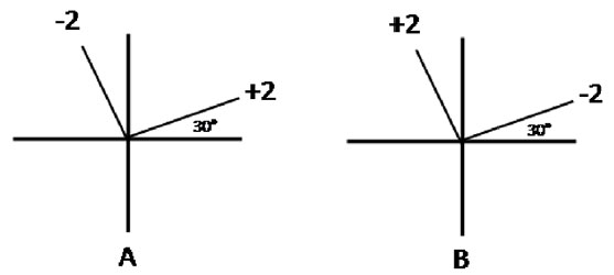
Traditionally, a cross diagram comprises a vertical and a horizontal line crossed in the middle. In this drawing, we insert the slopes and powers of the steepest meridians of the pair of the orthogonal cylinders that characterize ametropia correction (Fig. 1). Perhaps, the use of the steepest meridians could be attributed to the fact that they are the only ones that carry the power credited to the cylinder. Nevertheless, the primary issue encountered when working with these meridians is that the diagram does not provide the positions of the cylinder axes, which is critical information for transcribing optical prescriptions. Hence, cumbersome calculations often become mandatory to access this information. This study aims to present a straightforward and easier alternative for constructing a cross diagram, devoid of any nuisance.
CLASSICAL CROSS DIAGRAM
Diagram A of Figure 1 exemplifies the classical cross diagram, which expresses the power and inclination of the steepest meridians of the orthogonal cylinders that correct the refractive error. In the drawing, the +2 cylinder presents the steepest meridian at 30 and the –2 cylinder presents the same meridian at 120. Hence, this diagram leans on the position of the steepest meridians of the cylinders that correct ametropia 1.
The problem with the diagram A is that it does not reveal the direction of the cylinders axes (Fig. 1A), which is critical information for transcribing optical prescriptions. This limitation is a direct result of the violation of the principle that the axis of the cylinder is what characterizes the cylinder position 2. As the axes are always perpendicular to the steepest meridians, to find them it is necessary to change the directions shown in diagram A by 90º. By adding 90º to the inclination of the + 2 cylinder, we obtain the direction of its axis, which is 120º. Subtracting 90º from the direction of the steepest meridian of the 2 cylinder, we get the inclination of its axis, which is 30º. The transcription of this diagram in a combination of cylinders results in +2 cyl 120 –2 cyl 30. Despite being simple, this calculation might often become mentally draining, especially when the pair of the corrective cylinders makes an angle with the diagram., as mentioned above.
CROSS DIAGRAM BASED ON THE AXES OF THE CORRECTIVE CYLINDERS
Diagram B of Figure 1 shows the same cylinders as diagram A but expressed by their axes rather than by their meridians of maximum curvature The tilted line to the left corresponds to a cylinder of + 2 D whose axis is at 120° and the line to the right, a cylinder of 2 D whose axis is at 30º. It is notable that the steepest meridians (not shown in the drawing) retain their original positions, which is the very fact that validates the algebraic operations of the cross diagram based on the axes of the cylinders. In addition, diagram B reproduces the position of the focal lines of the refractive error because of the obligatory alignment of the corrective cylinders with the focal lines of the Sturm’s interval that defines ametropia. While a positive sign indicates that the focal line is beyond the retina, a negative sign implies that the focal line is inside the eye. By operating with the cylinders’ axes, this diagram can be transformed to optical prescriptions directly with no requirement for angular transpositions.
INTERPRETATION OF THE CROSS DIAGRAM BASED ON THE AXES OF THE CORRECTIVE CYLINDERS
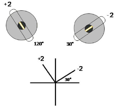
The cross diagram based on the axes of the cylinders depicts the powers and axes of the cylinders that neutralize the refractive error (Fig. 2). Two orthogonal cylinders of the same power and sign constitute a spherical lens (Fig. 2B and D). However, two orthogonal cylinders with different power and sign signify a spherocylindrical (toric) lens (Fig. 2A). Furthermore, two orthogonal cylinders, where one of them has zero value, correspond to a simple cylindrical lens (Fig. 2C and E).
Diagram A at the center of Figure 2 represents a lens that admits three interpretations: a combination of two cylinders, a combination of a positive sphere and a negative cylinder, and a combination of a negative sphere and a positive cylinder. The confirmation that diagram A is a combination of two cylinders is evident. We have only to read it literally, namely, + 2 cyl 120º x 2 cyl 30º. The combination of a positive sphere with a negative cylinder might be visualized as the association of a + 2 D sphere with a cylinder of 4 cyl 30°, identified as B and C respectively, in the upper part of Figure 2. By adding algebraically the optical power of the corresponding arms of B and C we obtain the lens A, which is transcribed as + 2 x 4 cyl 30º. The combination of a negative sphere with a positive cylinder might be envisioned as the association of a 2 D sphere with a single cylinder of + 4 cyl 30°, identified as D and E respectively, in the lower part of Figure 2. By adding algebraically the optical power of the corresponding arms of D and E we obtain the lens A, which is transcribed as - 2 x + 4 cyl 120º.
To construct a cross diagram from the corrective lens of a refractive error, we must proceed as follows: (1) Draw three cross diagrams, each of them with the pair of lines that will contain the axes of the orthogonal cylinders representing ametropia, as in A, B and C (or A, D and E) of Figure 2. Remember that any lens can be represented by a pair of orthogonal cylinders. (2) Convert the first diagram into a spherical lens by labeling both lines with the nominal value of the spherical component of the refractive error, as in B and D. (3) Convert the second diagram into a cylindrical lens by labeling the appropriate line with the power and axis of the cylinder that corrects astigmatism, ensuring the fellow line becomes identified with number zero, as in C and E. (4) Add algebraically the corresponding arms of these two diagrams and transfer the result to the empty diagram, which will display graphically the correction of ametropia, as in A.
Since a single cross diagram such as A of Figure 2, stands for different combinations of spheres and cylinders, it becomes a useful tool for transposing prescriptions of refractive errors into combinations of cylinders or cylinders and spheres.
RETINOSCOPY AND THE DIAGRAM BASED ON THE AXES OF THE CYLINDERS
In retinoscopy, an examiner compares the movement of a streak of light projected onto the eye surface with the retinal light reflex; the latter is the image formed by light reflected from the retina 3. When the cornea is toric, the retinal light reflexes, corresponding to the principal meridians of the cornea, coincide with the focal lines of the Sturm’s interval and, by extension, with the axes of the cylinders that correct ametropia 4. Thus, if one of the retinal light reflexes is at 120 and the lens necessary to neutralize it is a +2 cylinder, a correction of +2 cyl 120 is needed to conjugate the corresponding focal line to the peephole of the retinoscope. In the cross diagram, we record this cylinder in the direction of 120 (Fig. 3). If the other retinal light reflex requires –2 cylinder to neutralize it, a correction of –2 cyl 30 is needed to conjugate the matching focal line to the peephole of the instrument. In the cross diagram, we record this cylinder in the direction of 30 (Fig. 3). It is imperative to highlight here that this type of annotation varies from the classical one by 90.
REFERENCES
1. Rubin M. Optics for Clinicians. 2nd ed. Gainesville, FL: TRIAD Scientific Publisher, 1977, p.85.
2. Faria-e-Sousa SJ, Alves MR. Astigmatism: Aberration or ametropia? eOftalmo. 2018; 4 (1): 26-32. http://dx.doi.org/10.17545/eoftalmo/2018.0004
3. Corboy JM. The Manual Book - a manual for beginners. 2nd ed. Thorofare, NJ: Charles B Slack Inc, 1982.
4. Faria-e-Sousa SJ. Retinoscopia. In: Refratometria ocular e a Arte da Prescrição Médica. Alves MR ed. 3 ed. Rio de Janeiro, RJ: Cultura Médica, 2013. p. 5-15.

Funding: No specific financial support was available for this study.
CEP Approval: Not applicable
Disclosure of potential conflicts of interest: None of the authors have any potential conflict of interest to disclose.
Received on:
May 21, 2018.
Accepted on:
June 11, 2018.
 eOftalmo está licenciada com uma Licença Creative Commons Atribuição-NãoComercial 4.0 Internacional.
![]() © 2026 Todos os Direitos Reservados
© 2026 Todos os Direitos Reservados

 Ler em português
 Português PDF
 Imprimir
 Enviar este artigo por email
 Como citar este artigo
 Enviar um comentário
 Mendeley
 Pocket